


All Products
-
Servo Electric Cylinder
-
Linear Electric Cylinder
-
Linear Servo Actuator
-
Heavy Duty Electric Cylinder
-
Servo Press Machine
-
Servo Driven Press
-
Servo Electric Press
-
Robot 7 Axis
-
Robot Linear Track
-
Robot Rail System
-
Motor Assembly Line
-
Linear Drive Unit
-
Rack And Pinion Unit
-
German Made CNC Machines
-
Ball Screw Spindles
Contact Person :
Fiona Luo
Phone Number :
+86 18013106371
Whatsapp :
+8618000732351
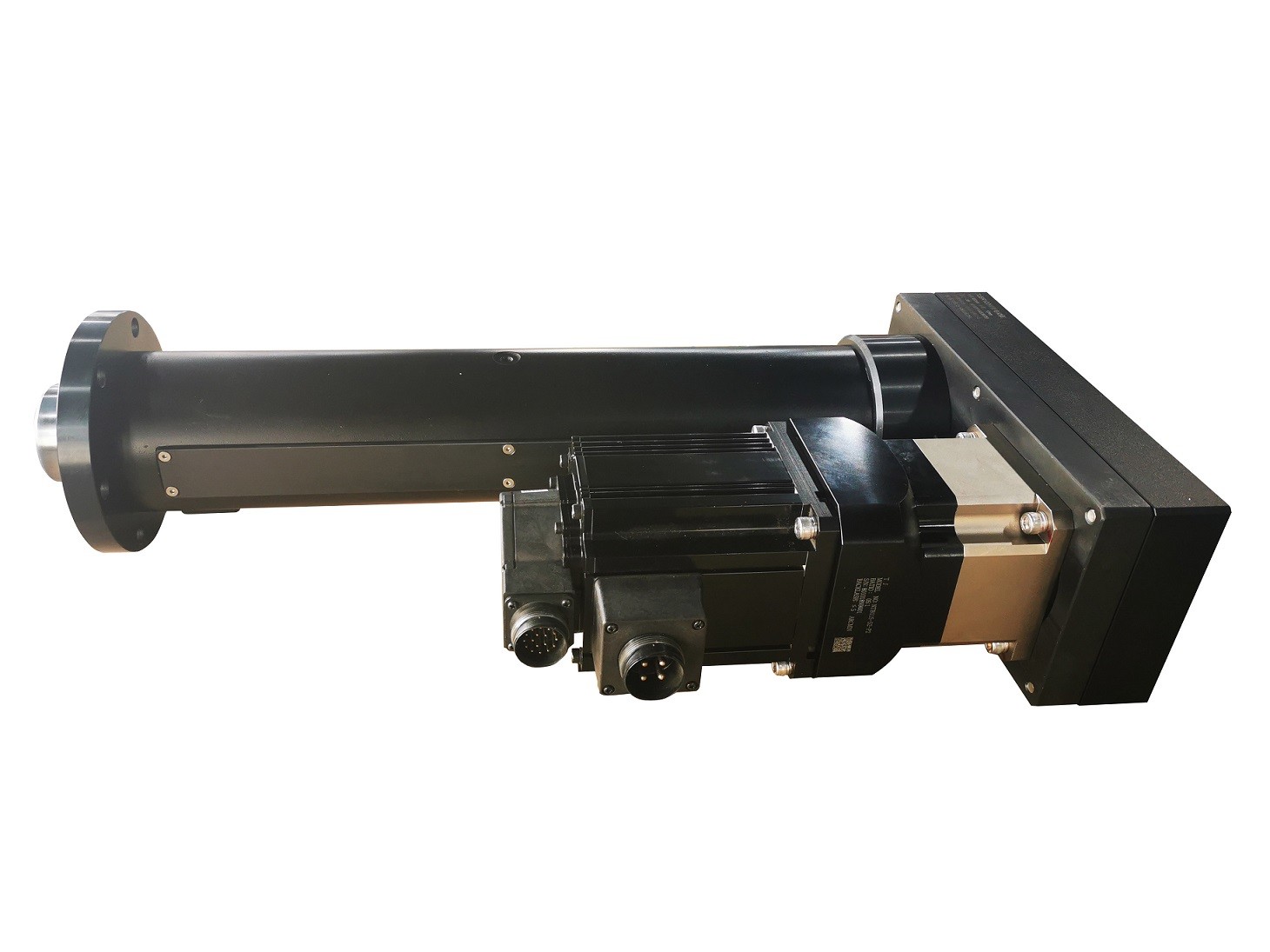
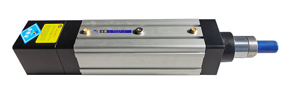
50-3000mm Servo Electric Cylinder With Control System / 0-500KN Linear Actuator Factory Outlet

| Place of Origin | China |
|---|---|
| Brand Name | TJ |
| Certification | ISO9001:2008,CE |
| Model Number | TJE075 |
| Minimum Order Quantity | 1 pcs |
| Price | negotiable |
| Packaging Details | external packing:carton or non wooden box;cushion packing:EPE foam |
| Delivery Time | 3-4 weeks |
| Payment Terms | T/T,30% payment in advance,70% before delivery |
| Supply Ability | 800 pcs per month |

Contact me for free samples and coupons.
Whatsapp:0086 18588475571
Wechat: 0086 18588475571
Skype: sales10@aixton.com
If you have any concern, we provide 24-hour online help.
xProduct Details
| Stroke | 50-3000 Mm | Speed | ≤ 1000mm/s |
|---|---|---|---|
| Repeatability | ±0.01mm | Output Force | ≤ 500KN |
| Motor Connection Type | Linear / Parallel / Bare | Internal Anti-rotation | With/without |
| Screw Lead | 4 , 5 , 8 ,10 , 20 , 40 Mm | Load Connection Type | Male,female,U-bolt,ball Head Hinge And Customized |
| High Light | Low Inertness Servo Electric Cylinder,High Rigidity Servo Electric Cylinder,500KN Servo Electric Cylinder |
||
Product Description
50-3000mm Servo Electric Cylinder With Control System / 0-500KN linear actuator factory outlet
1. Why choose us?
|
1. Compact structure and small dimension. |
|
2. High rigidity, low inertness and fast response. |
|
3. High reliability and long operating life. |
|
4. Energy saving&less noise. |
|
5. Convenient assembly and use,simple maintenance. |
|
6. One years of quality assurance, life - long maintenance service. |
2. Product Model Definition
Example: TJE075 S100 B R 05 A M C 2 P11 O/C N/P
|
TJE075—Series No.
TJE040:44×44mm TJE065:64×64mm TJE075:75×75mm TJE095:93×93mm TJE110:111×111mm TJE135:134×134mm |
S100—Effective Stroke
TJE040:50-200mm TJE065:50-250mm TJE075:50-600mm TJE095:50-800mm TJE110:50-1000mm TJE135:50-1200mm |
B—Screw Type
A:Acme Screw B:Ball Screw C:Roller Screw |
|
R—Anti-rotation
R:With T:Without(TJE040 always without this function )
|
05—Screw Lead
TJE040:4mm TJE065:4, 5, 10, 16,20mm TJE075:4, 5, 10, 20, 40mm TJE095:4, 5, 6, 8, 10, 25mm TJE110:5, 6, 8, 10, 20, 32mm TJE135:10, 20, 50mm |
A—Motor Mounting Type
B:Parallel |
|
M—Cylinder Mounting Type
M1:Double side mount M2:Side turnnion mount M3:Front flange mount M4:Rear flange mount M5:Rear clevis mount M6:Rear shaft mount MX:Customized
|
C —Load Connection Type
C1:Male C2:Female C3:U-bolt C4:Ball head hinge CX:Customized |
2—Number Of Limit Switches
(Default is normally open NPN switch) |
|
O/C—Limit Switches
O:Normally Open C:Normally Close
|
N/P—Sensing Type
N:NPN P:PNP |
|
|
Grating ruler + Force sensor |
|
Force sensor:① 4-20mA ② 0-10V Grating ruler:① TTL 24V ② RS422(5V Difference) |
|
If lacking of the part,it means without either grating ruler or force sensor. P01:Only with grating ruler TTL(24V) P10:Only with grating ruler 4-20mA |
Mark:
1) In order to ensure the effective stroke, two ends need to be reserved 5mm space.
2) The sensor couldn’t be mounted on the same side of the motor when the motor is parallel mounted.
3. Model Selection Guidances
STEP 1 :Accuracy & environmental condition
Check the basic conditions used in the application
STEP 2: Required space
Check the available space in the application and select the installation options: linear type,parallel type or bare cylinder.
STEP 3: MAX axial force required
Check the axial force to select the servo motor and gearbox(if necessary).
STEP 4: MAX speed
Check the required speed to select the screw lead.
STEP 5: Required stroke
Select the required stroke from a list of standard stroke.If the required stroke is not listed: define the length of the available stroke at a minimum of 10 mm.Note the value of the maximum possible travel of the selected model.
STEP 6: Lateral force
Determine the lateral force of the application.The new series of cylinders are allowed to bear some lateral force.Please communicate with us if you need to bear the lateral force in your application.
STEP 7 :Motor mounting flange
Select the appropriate motor mounting flange, linear or parallel.
STEP 8: The push-rod load form
Selects the electric cylinder push-rod end for load connection.
We also provide customized solutions!
4. Application areas:
★ Military equipment:radar, missile erector, armored vehicle swing platform, special equipment and other warships and aircraft hatch,opening, seat height adjustment, weapon tracking system,actuator,experimental lifting support, tank artillery high and low direction action adjustment, The push of rocket fuel, the opening of furnace door, etc.
★ Special equipment:industrial automation production line, assembly line, logistics transmission, lifting platform, offset control, valve control, coordinate manipulator, mechanical equipment CT Kama knife, food and medicine industry, CNC machine tools, industry packaging machine, Automotive electronic press, textile equipment winding machine indexing, die position control, clamping, drilling, positioning.
★ Experimental Equipment: Simulation platform, test bed, wave machine, testing equipment etc.
Recommended Products